Description
Introduction of PCB Designs in Altium
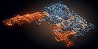
PCB Designs in Altium Training is one of the industry-leading electronic design automation (EDA) tools. Participants will learn the complete design process, from schematic creation to PCB layout, routing, simulation, and preparation for manufacturing. Through hands-on exercises, they will gain practical experience in creating reliable and manufacturable PCBs, focusing on best practices for multi-layer design, signal integrity, and design validation.
Prerequisites of PCB Designs in Altium
- Basic Knowledge of Electronics and Circuit Design (Ohm’s law, resistors, capacitors, etc.)
- Familiarity with Schematic Capture Tools (recommended but not required)
- Experience with CAD Software (beneficial for layout tasks)
- Windows OS Usage Skills (for software installation and interaction)
Table of Contents
1: Overview of Altium Designer and PCB Design Concepts
1.1 Introduction to PCB Design Workflows
1.2 Key Features and Advantages of Altium Designer
1.3 PCB Design Terminology: Traces, Vias, and Layers
1.4 Software Installation and Project Setup
2: Schematic Capture and Circuit Design
2.1 Creating a New Schematic Project(Ref: Altium Designer for Beginners)
2.2 Adding and Connecting Components
2.3 Wiring Techniques and Electrical Rule Checks (ERC)
2.4 Hierarchical and Multi-Sheet Designs for Complex Projects
3: PCB Layout and Board Setup
3.1 Defining the Board Outline and Layer Stack Manager
3.2 Component Placement Techniques for Optimal Layout
3.3 Routing Traces: Single-Layer and Multi-Layer Boards
3.4 Working with Vias, Polygons, and Copper Planes
4: Design Rules and Constraints
4.1 Introduction to Design Rules and Constraints Manager
4.2 Defining Electrical, Clearance, and Routing Constraints
4.3 Automatic and Manual Routing Techniques
4.4 Running Design Rule Checks (DRC) and Fixing Violations
5: 3D PCB Design and Mechanical Integration
5.1 Visualizing PCBs in 3D View Mode
5.2 Integrating Mechanical Layers and Design Data
5.3 Exporting 3D Models for Mechanical CAD (STEP files)
5.4 Collaborating with Mechanical Engineers
6: Signal Integrity, Simulation, and Testing
6.1 Introduction to Signal Integrity in PCB Design
6.2 Configuring Simulations for Signal and Power Analysis
6.3 Thermal Analysis and Power Distribution Networks
6.4 Tools for Testing and Debugging PCBs
7: Documentation and Manufacturing Files
7.1 Generating Fabrication Files: Gerbers, NC Drill Files
7.2 Creating Assembly Drawings and Documentation Sets
7.3 Bill of Materials (BOM) Management and Export
7.4 Preparing Pick-and-Place Files for Production
8: Design for Manufacturing (DFM) and Industry Standards
8.1 DFM Principles for Reliable PCB Production
8.2 Understanding IPC Standards and Certifications
8.3 Preparing for Assembly and Manufacturing Communication
8.4 Case Studies of Manufacturing Issues and Solutions
9: Advanced PCB Design Techniques
9.1 High-Speed Design: Guidelines for DDR and RF Circuits
9.2 Designing Flexible and Rigid-Flex PCBs
9.3 Creating Design Variants for Product Families
9.4 Using Scripts and Automation for Productivity
10: Final Project and Presentation
10.1 Overview of the Final Project: Multi-Layer PCB Design
10.2 Step-by-Step Guidance Through the Design Process
10.3 Presentation and Feedback on Final Projects
10.4 Q&A and Wrap-Up
Conclusion
This training equips participants with the knowledge and practical skills to design professional, manufacturable PCBs using Altium Designer. From schematic capture to layout, routing, and manufacturing file generation, participants will master the complete PCB design workflow and apply best practices to real-world projects.


Reviews
There are no reviews yet.